OpenSCAD is a program used to make 3D models. But unlike most 3D modeling programs, there are only 10 things you need to know in order to be dangerous in OpenSCAD. Unlike most other 3D modeling programs like Blender, Sketchup, AutoCAD, or Solidworks, it’s really easy to get started in OpenSCAD.
Another difference is that you write a programming language to do your 3D modeling. “I’m not a programmer, you say!” Actually, OpenSCAD is a declarative language, like HTML. If you’ve ever written a simple blog post or email in HTML, you can handle OpenSCAD.
In addition, it’s a 3D modeling program based on constructive solid geometry (CSG), which means you’ll never make models with holes in the resulting 3D model mesh (however, you can still make bad models in another way). Holes in the 3D model makes it indigestible by slicing programs like skeinforge and slic3r, and hence, unprintable.
Lastly, unlike many 3D modeling or CAD programs, it’s entirely free! Not just free of charge, but it’s open source with a vibrant community.
So what are the 10 things you need to know? They are in 3 simple categories: shapes (cube, sphere, cylinder), transforms (translate, scale, rotate, mirror), and CSG operations (union, difference, intersection).
As a result, all you do in OpenSCAD is declare shapes, change them with transforms, and combine them with set operations. After we do a quick run down of the 10 things, we’ll combine them to make a bishop chess piece.
Shapes
There are only three basic 3D shapes you start with, and from these, you can make most any other shape. These are the cube, the sphere, and the cylinder.
1) Cube
The cube is pretty simple. You declare it with:
cube([10, 20, 15]);

Don’t forget the semicolon! Now, there’s a cube with length 10, width 20, and height 15–each corresponding to each of the x, y, and z axis directions. In OpenSCAD if you refer something to be done along the x, y, and z directions, it will likely be in a vector, which is represented by numbers in brackets, like [x, y, z];
If you’d like a centered cube, that’s also pretty easy:
cube([10, 20, 15], center = true);
Easy, right?
2) Sphere
The sphere is pretty simple as well. You only have to declare the radius.
sphere(r = 20);

That gives you a sphere with a radius of 20. Notice that it’s centered at the origin already, unlike the cube.
Even easier.
3) Cylinder
The cylinder is a bit more complicated, but not by much.
cylinder(h = 40, r1 = 20, r2 = 20);
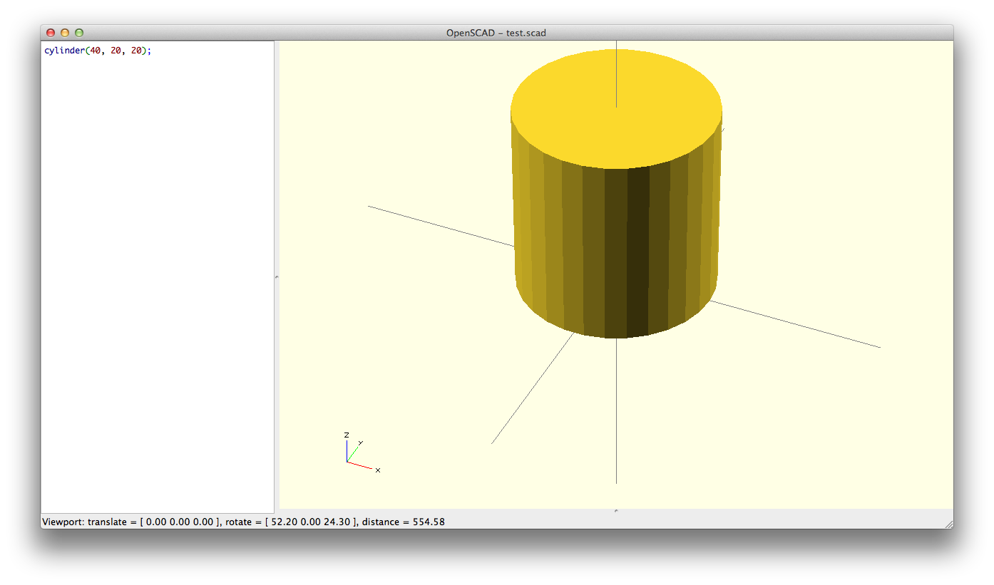
This gives us a cylinder of height 10, and a radius of 20. Notice that unlike the cube, the parameters aren’t in a vector, because each of the numbers don’t correspond to the x, y, and z axis. Why is 20 repeated twice? It’s because there’s the radius of the top and bottom circles. If you don’t want to specify the radius twice, we can do this instead:
cylinder(h = 40, r = 20);
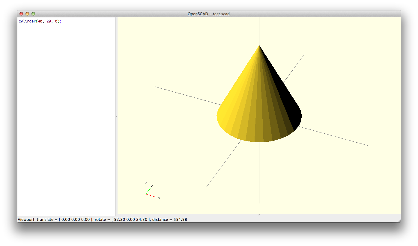
What if one of the radius was zero? Well, we’d get a cone instead by doing:
cylinder(h = 40, r1 = 20, r2 = 0);
And like the cube, if you’d like to center it, all you have to do is add another parameter called ‘center’:
cylinder(h = 40, r = 20, center = true);
A bit harder, but still grade school stuff.
Transformations
Transformation is just a fancy way of saying moving and stretching something. The terminology is borrowed from linear algebra, which is the math behind most 3D modeling, so don’t be weirded out by it. There’s only four basic ways to transform a shape: translating (moving), mirroring (reflecting), scaling (stretching), and rotating.
4) Translate
Translation means moving an object by some amount along the x, y, and z axis. Remember that sphere that was centered? What if we wanted its south pole to be at the origin? Well, we’d translate (ie. move it up) along the z-axis by its radius. To do that, we do:
translate([0, 0, 20])
  sphere(r = 20);

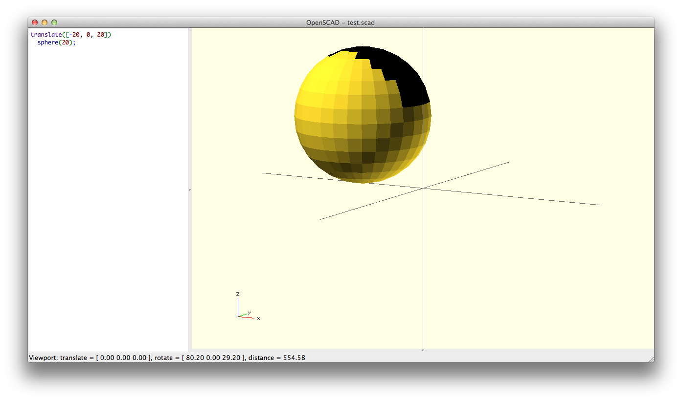
Easy! And if we wanted to also move it along the x-axis in the opposite direction, we use negative numbers.
translate([-20, 0, 20])
  sphere(r = 20);
5) Scaling
Scaling is just shrinking or stretching a model along an axis. Taking our sphere again, say we want to make an ellipsoid.
scale([1.5, 1, 1])
  sphere(r = 20);
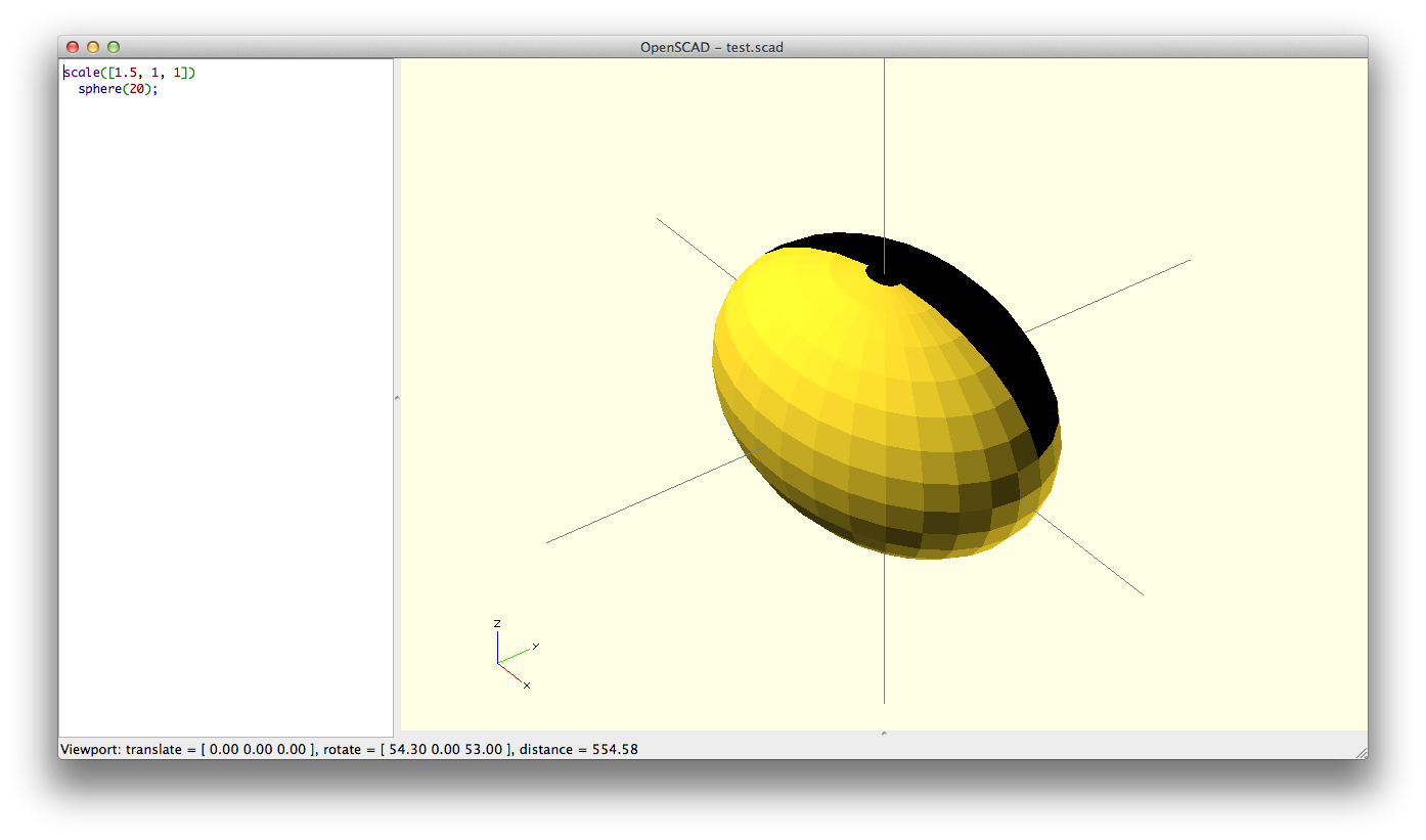
That will make an ellipsoid that is 1.5 times the original size along the x-axis. So we get an ellipsoid that has a length of 30 (20 * 1.5), and a width and height of 20.
If we use a number between 0 and 1, we will shrink the model. This will shrink the y-axis of the ellipsoid by half:
scale([1.5, 0.5, 1])
  sphere(r = 20);

Note that unlike translation, an unchanged axis in scaling is ‘1’, not ‘0’. If you put it ‘0’, it will scale that axis by zero, which will result in no model, because 0 * anything = 0.
6) Rotation
Rotation can get tricky, but easy if handled in steps. Let’s start with a cube and rotate it 45 degrees counter-clockwise around the z-axis.
rotate([0, 0, 45])
  cube([10, 20, 15]);

Like translation, if we want to rotate it in the opposite direction, we just use a negative number:
rotate([0, -30, 0])
  cube([10, 20, 15]);

What happens if we rotate two axis, like?:
rotate([45, -30, 0])
  cube([10, 20, 15]);
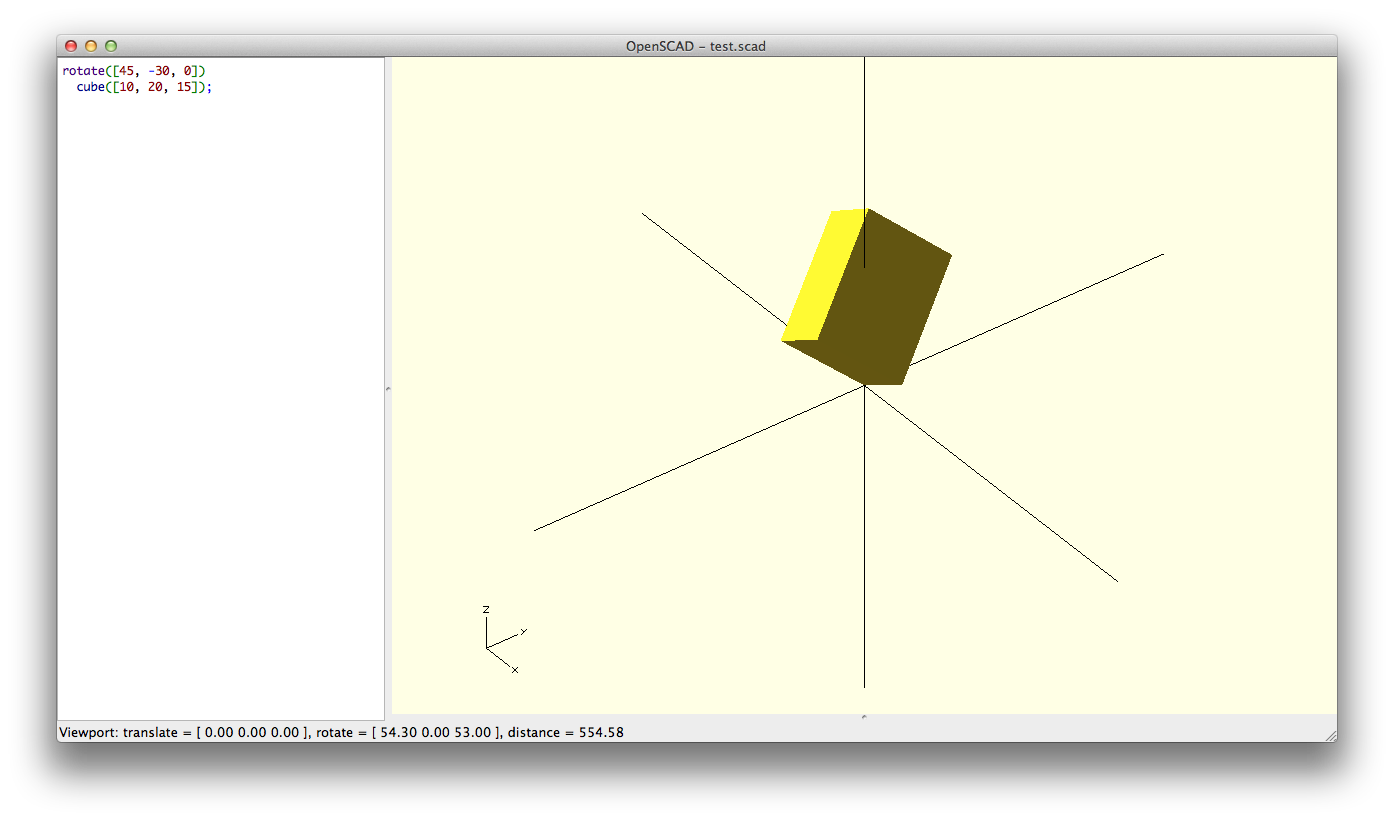
The way to think about this is that we first rotate around the x-axis first by 45 degrees, and then we rotate the result by 30 degrees around the y-axis.
Unlike translation and scaling, the order you apply the rotations makes a difference. Rotating first around the x-axis then the y-axis is NOT the same as rotating first around the y-axis then the x-axis. Hence, a rotate statement will always apply the rotations in the order, around x-axis, around y-axis, then around z-axis.
So what if we want to apply the rotations in a different order? Well, first, note that the previous rotation can be written as:
rotate([0, -30, 0])  // then applied second
  rotate([45, 0, 0]) // applied first
    cube([10, 20, 15]);
A 45 degree rotation is applied first, before applying the 30 degree rotation. The inside-most rotate() wrapping cube() gets applied first, then the outside rotate() gets applied second. So if we want the rotation applied to the y-axis first, then the x-axis, we just switch the two rotate statements:
rotate([45, 0, 0])    // switched these
  rotate([0, -30, 0]) // two lines
    cube([10, 20, 15]);

So far so good? This is the hardest of the four transformations. If you get this one, everything else is a breeze.
7) Mirroring
The last transformation is to reflect an object across the other side of a plane. Any plane is uniquely defined by vector perpendicular to it, called a normal vector. So to mirror across the yz-plane, the yz-plane is defined by the normal vector, [1, 0, 0].
First we’ll put a rotated cube, and then we’ll mirror a copy of across the yz-plane:
// rotated cube
rotate([0, 30, 0])
  cube([10, 20, 15]);
// mirrored across the yz-plane
mirror([1, 0, 0])
  rotate([0, 30, 0])
    cube([10, 20, 15]);

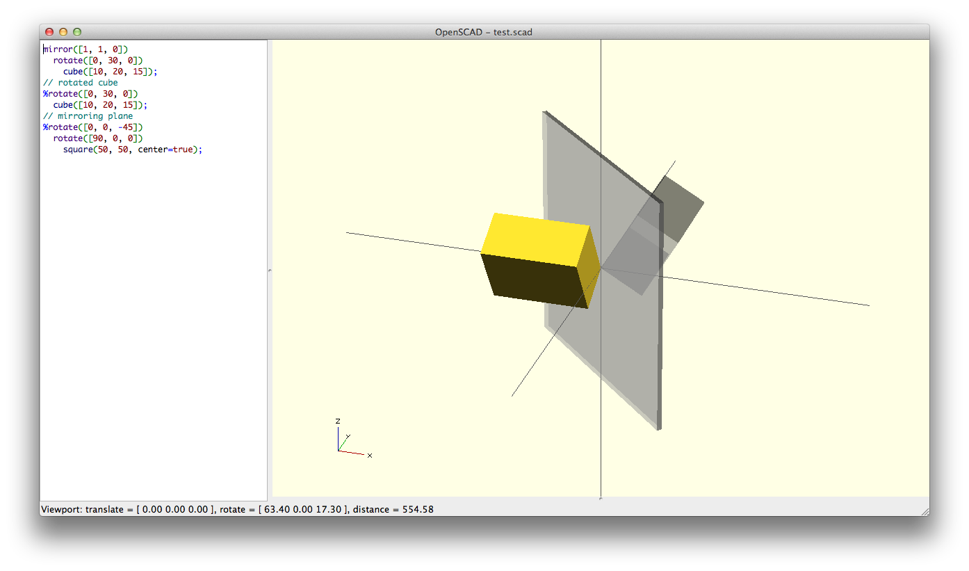
So if we have a normal vector of [1, 1, 0], the mirroring plane cuts at a 45 degree, as illustrated.
mirror([1, 1, 0])
  rotate([0, 30, 0])
    cube([10, 20, 15]);;

CSG Operations
Constructive solid geometry operations is just a fancy way of saying how we should combine shapes. If you remember sets from math class, that will probably help. But even if it doesn’t, the concepts are pretty simple.
8) Union
The simplest of the three set operations is union. Union is the sum of all shapes between its brackets.
union() {
  cylinder(h = 40, r = 10, center = true);
  rotate([90, 0, 0])
    cylinder (h = 40, r = 9, center = true);
}

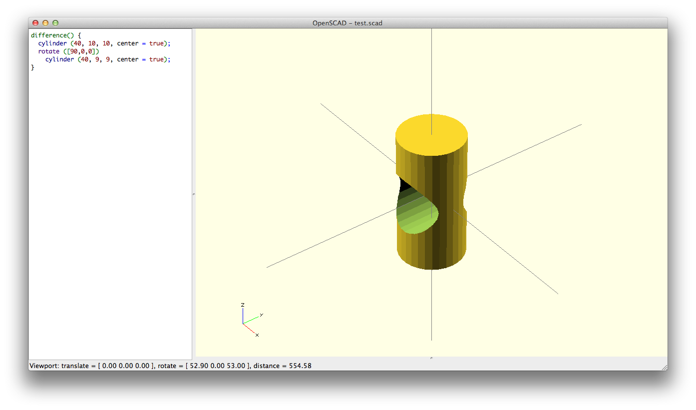
9) Difference
Difference is using the second shape (and all subsequent shapes in the bracket) to cut out from the first shape.
difference() {
  cylinder(h = 40, r = 10, center = true);
  rotate([90, 0, 0])
    cylinder(40, r = 9, center = true);
}
10) Intersection
Intersection is a little weird. It’s the overlapping part of all shapes between the brackets.
intersection() {
  cylinder(h = 40, r = 10, center = true);
  rotate([90, 0, 0])
    cylinder(40, r = 9, center = true);
}

Applying our new skills: bishop chess piece
Pretty easy so far, right? Now we’ll apply what we learned to make a bishop chess piece.
First, we want a teardrop shape of the bishop head. Let’s start with a sphere.
sphere(r = 20);


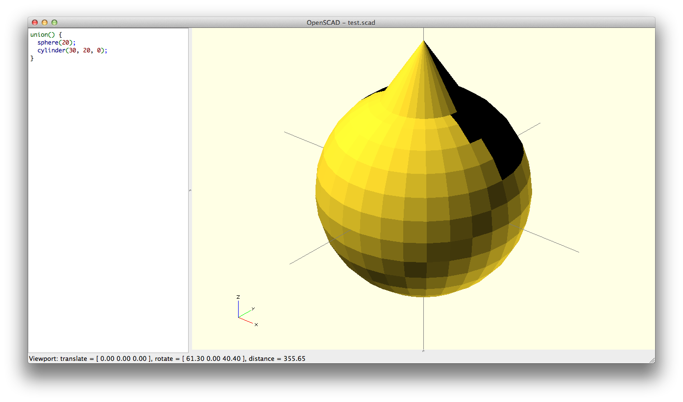
Then we add a cone to the sphere.
union() {
  sphere(r = 20);
  cylinder(h = 30, r1 = 20, r2 = 0);
}
However, we want the radius of the cone to match up with the radius of the sphere at a given height we move up the cone. We can use sin and cos to figure that out.
union() {
  sphere(r = 20);
  translate([0, 0, 20 * sin(30)])
    cylinder(h = 30, r1 = 20 * cos(30), r2 = 0);
}

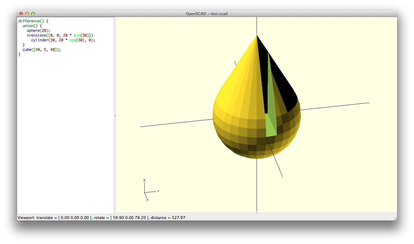
Now we have our teardrop shape, let’s cut the slot in the bishop’s head. First we have to make the slot as a rectangle, and cut it out.
difference() {
  union() {
    sphere(r = 20);
    translate([0, 0, 20 * sin(30)])
      cylinder(h = 30, r1 = 20 * cos(30), r2 = 0);
  }
  cube([40, 5, 40]);
}
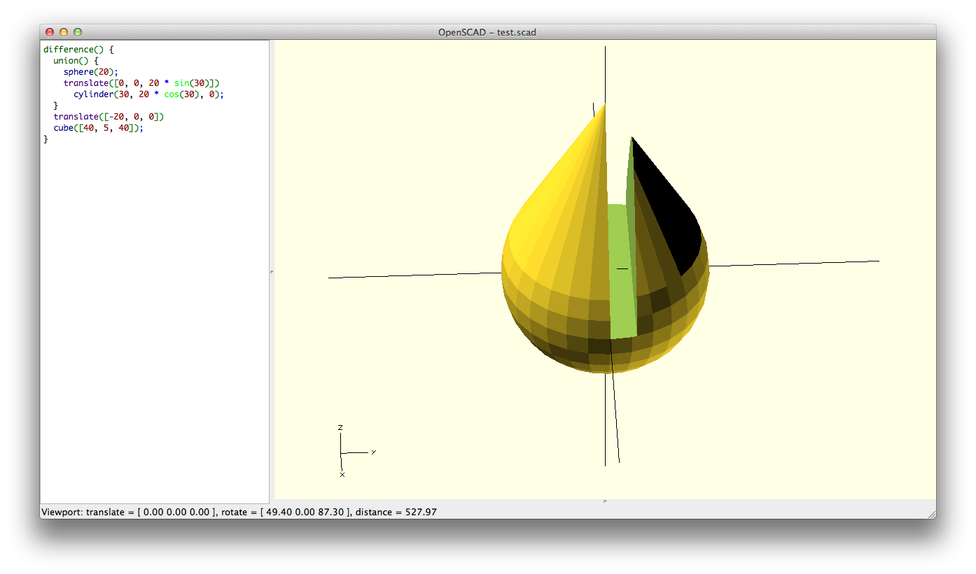
But the slot isn’t in the right place, so we’ll have to center it first.
difference() {
  union() {
    sphere(r = 20);
    translate([0, 0, 20 * sin(30)])
      cylinder(h = 30, r1 = 20 * cos(30), r2 = 0);
  }
  translate([-20, 0, 0])
    cube([40, 5, 40]);
}
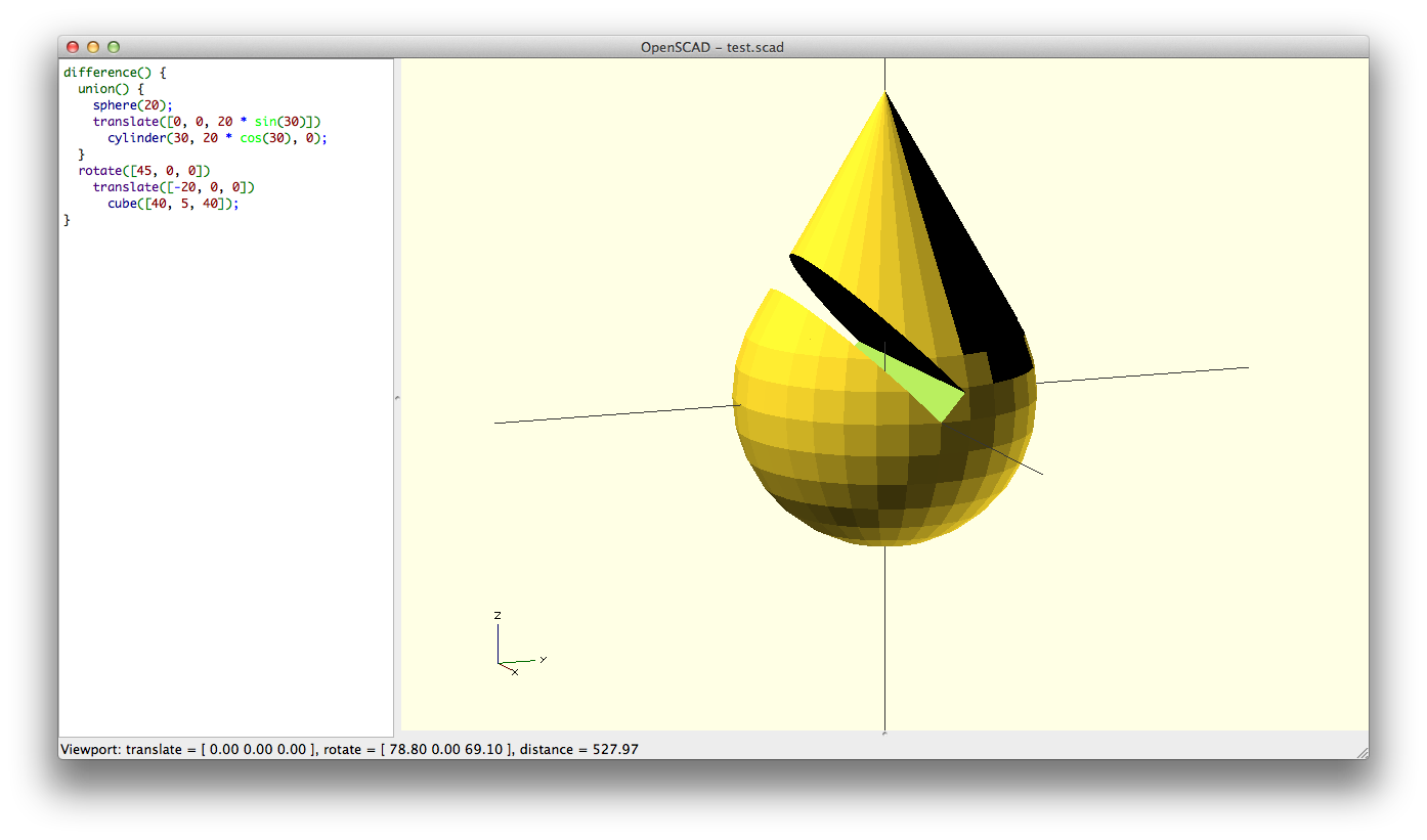
And then we rotate it by 45 degrees.
difference() {
  union() {
    sphere(r = 20);
    translate([0, 0, 20 * sin(30)])
      cylinder(h = 30, r1 = 20 * cos(30), r2 = 0);
  }
  rotate([45, 0, 0])
    translate([-20, 0, 0])
      cube([40, 5, 40]);
}
Now, let’s add a dollop on top. Since we know the height of the cone is 30, and we moved it up 20 * sin(30), we’ll need to translate the dollop 30 + 20 * sin(30). We’ll also comment the parts so we don’t get confused.
difference() {
  union() {
    // teardrop shape
    sphere(r = 20);
    translate([0, 0, 20 * sin(30)])
      cylinder(h = 30, r1 = 20 * cos(30), r2 = 0);

    // dollop
    translate([0, 0, 30 + 20 * sin(30)])
      sphere(r = 6);
  }
  //cut out slot
  rotate([45, 0, 0])
    translate([-20, 0, 0])
      cube([40, 5, 40]);
}

We need the bishop to have a neck and a base. Let’s keep it simple and use cylinders. We’ll lift the head up, and put a neck and base underneath.
union() {
  // head
  translate([0, 0, 120])
    difference() {
      union() {
        // teardrop shape
        sphere(r = 20);
        translate([0, 0, 20 * sin(30)])
          cylinder(h = 30, r1 = 20 * cos(30), r2 = 0);

        // dollop
        translate([0, 0, 30 + 20 * sin(30)])
          sphere(r = 6);
      }
      //cut out slot
      rotate([45, 0, 0])
        translate([-20, 0, 0])
          cube([40, 5, 40]);
    }
  // neck
  cylinder(h = 120, r1 = 18, r2 = 12);

  // base
  cylinder(h = 20, r1 = 35, r2 = 25);
}

It looks a little naked. Lastly, let’s put a collar on the bishop. To make a collar, we’ll intersect a cone with an inverted version of itself. We first start with a cone with its mirror.
cylinder(h = 20, r1 = 20, r2 = 0);
mirror([0, 0, 1])
  cylinder(h = 20, r1 = 20, r2 = 0);

Then we’ll take the mirrored version and shift it up, then take the intersection.
intersection() {
  cylinder(h = 20, r1 = 20, r2 = 0);
  translate([0, 0, 7])
    mirror([0, 0, 1])
      cylinder(h = 20, r1 = 20, r2 = 0);
}

Putting it together with the rest of it, we get:
union() {
  // head
  translate([0, 0, 120])
    difference() {
      union() {
        // teardrop shape
        sphere(r = 20);
        translate([0, 0, 20 * sin(30)])
          cylinder(h = 30, r1 = 20 * cos(30), r2 = 0);

        // dollop
        translate([0, 0, 30 + 20 * sin(30)])
          sphere(r = 6);
      }
      //cut out slot
      rotate([45, 0, 0])
        translate([-20, 0, 0])
          cube([40, 5, 40]);
    }
  // neck
  cylinder(h = 120, r1 = 18, r2 = 12);

  // base
  cylinder(h = 20, r1 = 35, r2 = 25);

  // collar
  translate([0, 0, 90])
    intersection() {
      cylinder(h = 20, r1 = 20, r2 = 0);
      translate([0, 0, 7])
        mirror([0, 0, 1])
          cylinder(h = 20, r1 = 20, r2 = 0);
    }
}

And that’s it! That’s really all you need to know to get started and get dangerous in OpenSCAD. If you would like to see how other chess pieces were written, check out king’s gambit, my first 3D printed project using OpenSCAD. If you’d like to learn more, check out a previous more advance tutorial on how to generate patterns from images with OpenSCAD.
Let me know if you find these helpful. Just follow me on twitter.
Update: For those of you curious about how the tangent cone’s dimensions were calculated. Start with theta. Then calculate the hypotenuse from r and theta (the red). Then calculate the height of the cone from the hypotenuse. The base radius of the cone is easy to calculate from theta, based on high school math. If you don’t know, hit me up on twitter.


well written 🙂
Thanks! Let me know if there’s other OpenSCAD topics you’d like to learn about.
Thanks for the writeup. It helped me with a nightmare I was having trying to convert STL into a solid object.
No problem! Let me know if there are other posts you’d like to read. I’ll write it if I can!
Hello
Nice tutorial.
When intersecting and diffing, It’s better not to create zero-thickness zones. I had problems with that.
I can second Sebastien’s comment.
Having coincident faces and doing boolean difference operation can flip the normals
of faces.
Better to avoid that …
I kept it out of a beginner’s tutorial, but I’ll put it on my list of OpenSCAD gotchas, like putting faces flush against each other in union()
Unless I am mistaken, the problem presents whether you use union() or not. The compiler has to make a solid out of the pieces and it is at that point that the problem occurs, not during the union() operation.
Right? You can’t eliminate the problem by eliminating the union() – you have to fix the faces.
yes, that’s correct. I meant that it can happen as well with union(), when someone decides to build a shape by butting up faces of shapes with union()
[…] I showed you how to extrude images in OpenSCAD, and a beginner’s guide to OpenSCAD. This time it’s a more advanced method on how to emboss images onto a surface in OpenSCAD, […]
iamwil – GREAT TUTORIAL! Thanks for doing it! I really appreciate it!
Hi, great tutorial. Can you please elaborate a little on the calculation to make the cone match the sphere at a give point?
Where did you get the 30ª corner from? How did you found the formulas? Math is so long ago ^^
Thanks! check this page out about the unit circle: http://www.mathsisfun.com/geometry/unit-circle.html
Look at the second picture. For a particular angle, we get a point on the circle for any given radius. In this case, the radius is 1. The cosine of that angle is the yellow line, aka how far along the x-axis that point on the unit circle is. The sine represents how far up the y-axis that point on the unit circle is, which is red.
so if we’re putting a cone on it, we can see that the base radius of the cone is the cosine, and how far we should lift it is the sine. If the circle is of a different radius other than 1, we just multiply the cosine or sine by the radius.
thank you very much for the explanation. What I didn’t understand is how you came up with the angle of 30 degrees and how this resulted in a cone height of perfect 30mm.
Or did you first chose the height of the cone and then calculated the angle which conveniently turned to be 30 degrees?
As long as the cos is not 0, the two tangents can form any cone with a height between 0 and almost infinite. The height of the cone (how far the two tangents meet) will decide the size of the angle and vice versa.
So the only thing was given was R_sphere. So you need to choose either an angle or a height. I was just curious which one you choose first and how come the other turned out to be an integer. Or do I miss something here?
I didn’t remember how I did the easier version of the calculation for 30 deg. But I worked out the generalized solution:
cone_height = r * tan(90 – theta) * sin(90 – theta)
cone_offset = r * sin(theta)
cone_radius = r * cos(theta)
where theta is the angle of the line from the origin to the tangent point. The angle between the cone base and the side is 90 – theta. The hypotenuse is r * tan(90 – theta). And hence, the height is r * tan(90 – theta) * sin(90 – theta). I drew up a picture for you to refer to at the end of the blog.
In addition, you often don’t have to do the calculation to do the tangent. In this case, you can actually use hull() to get a teardrop shape with a tangent.
hull() {
sphere(r = 20);
cylinder(h = 50, r1 = 5, r2 = 0);
}
However, I intended to cover hull() in a later tutorial. Hope that helps!
Thank man, I love your dedication! I just couldn’t stand the fact I couldn’t find out how you came up with the 30-30. I spent like a whole afternoon on it. 🙂 I kind of feel guilty now because it seems like you also spent quite some time on the answers.
I recommended your blog to a good friend who is an OpenScad beginner and it was him that pointed out the 30-30 ‘enigma’. Anyway, great second tutorial also! If you look for ideas for future tutorials maybe a little explanation on the necessity of using union() would be interesting. I have already made a few rather complex objects in openscad which I also successfully printed and never used union.
Sure, no problem. If you’re using OpenSCAD, check out Cubehero to host your 3D modeling projects.
In addition, I found this later: https://en.wikipedia.org/wiki/File:Circle-trig6.svg
It shows the height of the cone is also versin + exsec, or sec – cos.
Union is usually implied, and for the most part optional. If people get confused about it often, then I’ll write something up about it.
[…] you know the 10 things to be dangerous in OpenSCAD, and now you have the power to easily 3D model in your hands! However, for all but the simplest of […]
Awesome tutorial!
Do you perhaps know how to convert scad file to STL (or any other more common printable-file) automatically? i.e not using the export button?
Yes. You can do it through the command line:
openscad -o my.stl my.scad
Check out the export section of the manual
[…] Know only 10 things to be dangerous in openscad/ […]
I’m having some problems with rotate and translate. I’m well versed with order of operations, and rotation around the origin – so I’m a little confused as to what’s happening. I’m using version 2104.03 in Winbloze exPee.
I want to declare a simple cone, rotate it, and then translate it. Simple cone works fine. rotation works as predicted. The strange thing happens when I translate – it’s like the base of the declared cone is being translated along a line that’s been rotated with respect to the origin as well. I rotate the cone 22 deg around x, and then when I translate it along the y axis, it “goes uphill”. I changed the angle to 45, and it goes up a very steep hill. Is this a bug, or am I just wrapped in a know of my own misunderstanding of OpenSCAD’s syntax and order of operations?
Thanks for any assistance,
Bill
What’s your OpenSCAD code look like?
My guess is that you have the order of operations reversed. If you rotate your cone 22 degs first, and then translate it, it looks like:
translate([0, 10, 0])
  rotate([22, 0, 0])
    cylinder(h = 10, r1 = 10, r2 = 0);
You need to read it from the inside out.
Sorry, I was going to post some, but didn’t know what the rules were.
I’m sure it’s just a stupid (l)user error, as often happens when i don’t get enough sleep or coffee, or both. 😉
Here’s the relevant code block
// camera view(s)
cone_length = 11;
correction = 1;
yangle = 22;
xangle = 16;
%rotate ([yangle, xangle, 0])
translate([0, (height/2), -correction])
cylinder (h = cone_length, r1 = 0.1, r2 = (6.75/2), $fn = facets);
%rotate ([yangle, -xangle, 0])
translate([0, (height/2), -correction])
cylinder (h = cone_length, r1 = 0.1, r2 = (6.75/2), $fn = facets);
#translate ([0, height, -9])
cube ([width, height, 0.1], center = true);
%rotate ([(yangle+180), xangle, 0])
translate([0, (-height/2), correction*1.5])
cylinder (h = cone_length, r1 = 0.1, r2 = (6.75/2), $fn = facets);
%rotate ([(yangle+180), -xangle, 0])
translate([0, (-height/2), correction*1.5])
cylinder (h = cone_length, r1 = 0.1, r2 = (6.75/2), $fn = facets);
#translate ([0, -0, 9])
cube ([width, height, 0.1], center = true);
Here’s the whole scad file so far:
// Colors only render when using F5 option, not F6
// ———————————————–
inch = 25.4;
height = 6.75;
width = 10.75;
thickness = 0.37;
handle_size = 1.25;
facets = 36;
slices = 36;
shade = 0.2;
Ocolor0 = “yellow”;
Ocolor1 = “green”;
Ocolor2 = “red”;
pcolor = [1, 0.5, 0];
pdistance = 2;
scale(inch) Surface (); // Dummy Surface for visualization
scale(inch) Indicators (); // pointers to controls and ports for visualization
color(Ocolor2) scale(inch)
translate([8, 0.25, 0]) rotate ([90, 0, 0])
cover_handle (handle_size/2);
color(Ocolor2) scale(inch)
translate([-8, 0.25, 0]) rotate ([90, 0, 0])
cover_handle (handle_size/2);
module Surface() {
// Body
color ([shade,shade,shade])
cube ([10.75, 6.75, 0.37], center = true);
// Screen
color (“blue”)
translate([0, 0, 0.01])
cube ([9.25, 5.25, 0.38], center = true);
}
module Indicators() {
// Control indicators
pointer = 0.125;
p_length = 2;
color (pcolor)
union () {
// Microphones
translate([-(width/2)+3.5, (height/2)+pdistance, 0])
rotate ([-90, 0, 0])
cylinder (h = p_length, r = pointer, $fn = facets);
translate([(width/2)-3.5, (height/2)+pdistance, 0])
rotate ([-90, 0, 0])
cylinder (h = p_length, r = pointer, $fn = facets);
// Power button
translate([(width/2)-1.5, (height/2)+pdistance, 0])
rotate ([-90, 0, 0])
cylinder (h = p_length, r = pointer, $fn = facets);
// Left Speaker
translate([-(width/2)-pdistance, (height/2)-0.8, 0])
rotate ([0, -90, 0])
cylinder (h = p_length, r = pointer, $fn = facets);
translate([(width/2)+pdistance, (height/2)-0.8, 0])
rotate ([0, 90, 0])
cylinder (h = p_length, r = pointer, $fn = facets);
// Earphone jack
translate([-(width/2)-pdistance, (height/2)-1.37, 0])
rotate ([0, -90, 0])
cylinder (h = p_length, r = pointer, $fn = facets);
// Volume +/- button
translate([-(width/2)-pdistance, (height/2)-2.45, 0])
rotate ([0, -90, 0])
cylinder (h = p_length, r = pointer, $fn = facets);
// micro HDMI
translate([(width/2)+pdistance, (height/2)-1.37, 0])
rotate ([0, 90, 0])
cylinder (h = p_length, r = pointer, $fn = facets);
// USB indicator
translate([(width/2), (height/2)-2.2, 0])
rotate ([0, 90, 0])
cylinder (h = p_length*2, r = pointer, $fn = facets);
}; // end color union
// USB Stick
// plug-in part
usbplugx = 0.5; usbplugy = 0.48; usbplugz = 0.2;
translate([(0.25+(width/2)+pdistance*2), (height/2)-2.2, 0])
cube ([usbplugx, usbplugy, usbplugz], center = true);
// stick body
usbstickx = 2.8; usbsticky = 1; usbstickz = 0.35;
translate([( (width/2)+(pdistance*2)+(usbstickx/2)+usbplugx ), (height/2)-2.2, 0])
cube ([2.8, 1, 0.35], center = true);
//SD card
cardx = 1; cardy = 1.25; cardz = 0.09;
translate([((width/2)+(pdistance*2)+(usbstickx/2)+usbplugx), (height/2)-2.2+cardy, 0])
cube ([cardx, cardy, cardz], center = true);
// camera view(s)
cone_length = 11;
correction = 1;
yangle = 22;
xangle = 16;
%rotate ([yangle, xangle, 0])
translate([0, (height/2), -correction])
cylinder (h = cone_length, r1 = 0.1, r2 = (6.75/2), $fn = facets);
%rotate ([yangle, -xangle, 0])
translate([0, (height/2), -correction])
cylinder (h = cone_length, r1 = 0.1, r2 = (6.75/2), $fn = facets);
#translate ([0, height, -9])
cube ([width, height, 0.1], center = true);
%rotate ([(yangle+180), xangle, 0])
translate([0, (-height/2), correction*1.5])
cylinder (h = cone_length, r1 = 0.1, r2 = (6.75/2), $fn = facets);
%rotate ([(yangle+180), -xangle, 0])
translate([0, (-height/2), correction*1.5])
cylinder (h = cone_length, r1 = 0.1, r2 = (6.75/2), $fn = facets);
#translate ([0, -0, 9])
cube ([width, height, 0.1], center = true);
} // end module Indicators()
module cover_handle (radius) {
cylinder (h = height, r = radius, $fn = facets, center = true);
translate([0, 0, height/2]) sphere (radius, $fn = facets, center = true);
translate([0, 0, -height/2]) sphere (radius, $fn = facets, center = true);
} // end module handle()
// back
color ([1,1,0])
translate([0, 0.25*inch, (-thickness/2)*inch])
cube ([(width-0.1)*inch, (height+0.25)*inch, 1], center = true);
// top crossbeam
color ([1,1,0])
scale (inch)
translate([0, (height/2)+0.25, 0]) rotate ([0, 90, 0])
cylinder (h = 16, r = 0.25, $fn = facets, center = true);
// center crossbeam
color ([1,1,0])
scale (inch)
translate([0, (-height/2)+3.5, (-thickness/2)])
difference(){
rotate ([0, 90, 0])
cylinder (h = 16, r = 0.75/2, $fn = facets, center = true);
translate([0, 0, 1]) rotate ([0, 0, 90])
cube ([2, 16, 2], center = true);
}
color ([0,1,0])
scale (inch)
translate([0, (-height/2), 0])
difference(){
cube ([16, 0.75, 0.5], center = true);
scale (1/inch) Surface();
translate([0, 0.25, 0]) cube ([2, 0.5, 0.6], center = true);
}
//Right clip
color ([1,1,0])
scale (inch)
translate([(width/2), (-height/2)+3.5, -(thickness/2)])
difference(){
translate ([0,0,0.25]) cube ([0.5, 0.75, 0.5], center = true);
scale (1/inch) Surface();
}
Bill, lemme take a look at this tonight or tomorrow morning. It’s currently a bit busy here. 😉 But which part of the file exactly did you have a problem with?
The control indicators module has some cones representing ‘camera views’. It’s the cones that are acting strangely, translating along an incline, rather than along the axes. Been busy myself, learning Debian linux, arduino sketches, bash scripts, python, and perl. Just another day in the life… 😉 Thanks for taking a look. Take your time.
Sorry, I realized that the block of code I supplied didn’t render in a manner that exemplified the problem. Been having some issues with the desktop, so it will be a little while before I can post the whole scad file. I have a feeling that the problem will lie in the opening/closing parentheses… Does openscad have parentheses matching capability?
I stopped reading after you said OpenScad is easier to learn than blender, you have to be fucking kidding me.
There’s other parts of the internet for you. One man’s meat is another man’s poison.
[…] http://blog.cubehero.com/2013/11/19/know-only-10-things-to-be-dangerous-in-openscad/ […]
thanks Cube hero. You really are! can you provide more examples using for loop
What kind of examples were you hoping to see? You wanted to have some idea of all the different ways you can utilize a for loop?
I was working on the Tapered roller bearing and I needed for loop to make circle of small cylinders around. That was easy and I have done that :). I have question about surface smoothness. Why the surfaces are not smooth enough(after F6-rendering) in Openscad like free cad or other CAD softwares? Is there something wrong with my PC memory or I need to change different views? Please let me know if you got my question otherwise I will show you example with screenshots.
The smoothness can be controlled with the variable $fa and $fs. Look it up on the openscad manual, and you can see that you can set it globally at the top of your source, or locally, per shape.
yes I got it, Thanks. Well I think globally will slow the rendering process. Locally will be good what are your opinions?
Globally will be slow if there’s other shapes where you don’t need that kind of resolution. But also keep in mind that 3D printers have a resolution themselves, so really fine detail on the model may not matter. If you do local, I believe some modules, like sphere, take a $fa parameter.
Arshpreetsingh : While I don’t presently make extensive use of OpenSCAD, I have done a bit of programming, and a lot of POV-Ray Scene Description Language (SDL).
While the exact commands and syntax might differ slightly, the types and structure of loops are generally the same from language to language.
POV-Ray
http://wiki.povray.org/content/Knowledgebase:While_Loop_Tutorial
http://www.povray.org/documentation/view/3.6.0/114/
http://www.f-lohmueller.de/pov_tut/loop/povlup7e.htm
OpenSCAD
http://en.wikibooks.org/wiki/OpenSCAD_User_Manual/Conditional_and_Iterator_Functions
If you have tricky conditions, or nested loops, it’s easy to get “lost” in following the logic of what the loop actually does vs what you want it to do. It’s often a good idea to use some sort of “reporter variable” to be output to screen or file so that you can easily follow along with what your code is actually doing and easily debug it.
So, if you were using the loop in the OPENSCAD example above,
for ( i = [0 : 5] )
{
rotate( i * 360 / 6, [1, 0, 0])
translate([0, 10, 0])
sphere(r = 1);
}
What you might want to do is assign the result of the i*360/6 calculation to a variable, and then substitute that calculation with the variable in the rotate() command. You can then also output the variables value for all values of i so that you watch how the variable changes throughout the loop with each increment and iteration. When you’re done with getting your code to work properly, you can just comment out those lines if necessary so that you can refer to them when modifying the code, sharing it, or coming back to old code that you can’t remember the intricate details of.
Nice. Very easy. In two minutes I created a part I need. Now lets print it. Thank.
There is one very basic thing about this. It’s the basic unit. I suppose number 1 is simply 1mm, but is it set somewhere and is it possible to change this by some parameter? Or is it just fixed here and not possible tho change?
There’s nowhere to designate it in openscad. It just assumes units though most everyone uses mm.
[…] http://blog.cubehero.com/2013/11/19/know-only-10-things-to-be-dangerous-in-openscad/ […]
Superb article! I’m a web developer just getting started with 3D modelling. This approach seems second nature to how I’m used to working. This helped me make my decision to start with OpenSCAD. Thank you!
Thanks for the great tutorial and explanations! Easy to read and understand! I wonder if Openscad works with mathematical functions? For example, if I want to get an elliptic paraboloid x^2/a^2+y^2/b^2+z^2/c^2=1 with given a, b, c. Thank you in advance.
[…] Know only 10 things to be dangerous in OpenSCAD […]
Do you know if it is possible to change a rendering in real time with openscad? A file that change and the openSCAD render accordingly.
[…] http://blog.cubehero.com/2013/11/19/know-only-10-things-to-be-dangerous-in-openscad/ […]
“module” alleviates so many rotational problems that it is invaluable!!! When you rotate an object in the main body, all subsequent operations are with respect to the ROTATED axes! If you put the rotation in a module and then use the module in the main body, all subsequent operations are with respect to the NORMAL axes! Working with respect to the NORMAL axes is MUCH easier!!!
Blessings,
Art in Carlisle, PA USA
[…] http://blog.cubehero.com/2013/11/19/know-only-10-things-to-be-dangerous-in-openscad/ […]
how do i make hemisphere in openscad
is it possible making hemisphere or a boul in openscad
make a sphere. Then diff it against a cube translated down. (Or intersect it against a cube translated up)
thanx sir
how do i make object surface smooth
You can set the $fa, $fs, or $fn variables at the top of your script. They’re detailed here: https://en.wikibooks.org/wiki/OpenSCAD_User_Manual/Other_Language_Features#.24fa.2C_.24fs_and_.24fn
[…] in the list How to use OpenSCAD. It linked to several other tutorials, the most notable one being Know only 10 things to be dangerous in OpenSCAD as having the most compact words-to-content […]
I’m taking this opportunity to thank you for this post. It was one of the things that got me started using OpenSCAD a couple of years ago. I stumbled upon it again today while looking for a solution to a preview transparency issue which I found is basically issue #310 in the issue tracker. Oh well…
No problem. Glad to have helped.
This page was the one that really got me started with OpenSCAD when I got my first printer almost 3yrs ago. On Wednesday I’ll be running a 3D printing workshop for 28 people largely based on this as it’s so clear and helpful. Hope that’s ok! 5yrs after posting and this article is still an incredibly useful resource – thank you.
No problem, glad to help! Good luck on the workshop, and pay it forward.
[…] it. In the very first 10 minutes i just tried to understand the coding, functions, shapes from the tutorial that I followed. And then I came to know to where to start, it took me around the first 20 minutes […]
[…] mind and then translating this into distances and objects. A great tutorial on OpenSCAD is over here. Its power comes from using geometry in a Cartesian reference space to combine, intersect, and […]
This was great. I ended up using the polyhedron to do my build but this got me past the initial hump and i built my project in a couple of hours.
openscad beats the heck out of tinkercad if you’re trying to place things accurately.
Great write up, thank you!
[…] was also Clive’s entrance into the world of openSCAD. He includes the openSCAD script he created which you can cut, paste, and tweak to your own […]
[…] was also Clive’s entrance into the world of openSCAD. He includes the openSCAD script he created which you can cut, paste, and tweak to your own […]
Really great tutorial! Thanks!!!!
Cool tutorial